
Dies ist eine alte Version des Dokuments!
Inhaltsverzeichnis
CAN Bus Wiring Guide
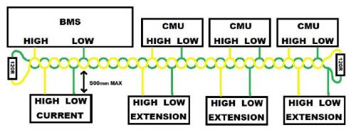
Proper CAN wiring is essential for stable communication between the BMS and connected devices like CMUs, inverters, chargers, etc.
Basic Wiring Rules
CAN uses two lines: HIGH (CAN-H) and LOW (CAN-L)
All devices are connected in parallel along one continuous bus line
No star topology or long branches – only short drop lines (max. 500 mm) to each device
Termination Resistors
A 120 Ω resistor must be placed at each end of the bus
The BMS and last CMU typically provide termination if configured correctly
Only two resistors total on the bus – no more, no less
⚠️ Missing or incorrect termination leads to unstable or no communication
Example Devices on the Bus
BMS: Master device
CMUs: Cell Management Units – multiple allowed
Other extensions: e.g. displays, current sensors, inverter Each device has a CAN HIGH / CAN LOW pair that must be connected to the main line.
🛠️ Make sure the CAN baud rate and ID settings  match across all devices on the bus

Check under Connections → CAN Bus  for configuration options