
mk3:wirringcan
Inhaltsverzeichnis
CAN Bus Wiring Guide
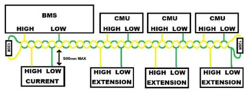
Proper CAN wiring is essential for stable communication between the BMS and connected devices like CMUs, inverters, chargers, etc.
Basic Wiring Rules
- CAN uses two lines:
HIGH(CAN-H) andLOW(CAN-L) - All devices are connected in parallel along one continuous bus line
- No star topology or long branches – only short drop lines (max. 500 mm) to each device
Termination Resistors
- A 120 Ω resistor must be placed at each end of the bus
- The BMS and last CMU typically provide termination if configured correctly
- Only two resistors total on the bus – no more, no less
⚠️ Missing or incorrect termination leads to unstable or no communication
Example Devices on the Bus
- BMS: Master device
- CMUs: Cell Management Units – multiple allowed
- Other extensions: e.g. displays, current sensors, inverter Each device has a CAN HIGH / CAN LOW pair that must be connected to the main line.
🛠️ Make sure the CAN baud rate and ID settings  match across all devices on the bus

Check under Connections → CAN Bus  for configuration options
mk3/wirringcan.txt · Zuletzt geändert: 2025/04/07 18:51 von grnbms_tech