
Dies ist eine alte Version des Dokuments!
1. Power Supply
The GRNbms MK3 supports both High Voltage (HV) and Low Voltage (LV) operation.
➤ Low Voltage Mode (12 V System)

- Connect 12 V to the „Jump Start“ connector
- This powers the BMS directly for low-voltage applications or setup/configuration
➤ High Voltage Mode
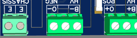
- For high-voltage setups, connect the BMS using the dedicated HV connectors
HV POS Connector:
B+→ Connect directly to Battery PositiveO+→ Output (post-relay) – not required for power supply
HV NEG Connector:
B-→ Connect directly to Battery NegativeO-→ Output (post-relay) – not required for power supply
✅ To power the BMS: only B+ and B- are needed
⚠️ Valid voltage range: 150 V – 1200 V DC Operating the BMS outside this range may cause malfunction or damage.
Additionally, for safety and EMI compliance:
- Connect the battery chassis to the
Epin on the CHASSIS connector - Use a dual connection if possible for redundancy
👉 Details about relay and output wiring can be found here
2. Network Connection
An internet connection is required for the initial setup and activation of your BMS.
➤ Ethernet Connection (recommended)
Connect the BMS to your local network using a standard RJ45 Ethernet cable
The BMS will automatically obtain an IP address via DHCP (from your router)
➤ Accessing the BMS
Once connected, try opening one of the following in your browser:
http://grnbmsmk3.local/''
💡 These names work only if your router supports mDNS or local hostname resolution.
➤ Can’t find your BMS?
No problem – just visit grnbms.de**.
There you can:
See all BMS devices in your local network
Follow the guided setup instructions