
mk3:minipinout
Dies ist eine alte Version des Dokuments!
Inhaltsverzeichnis
GRNbms MK3 Mini – Wiring & Pinout
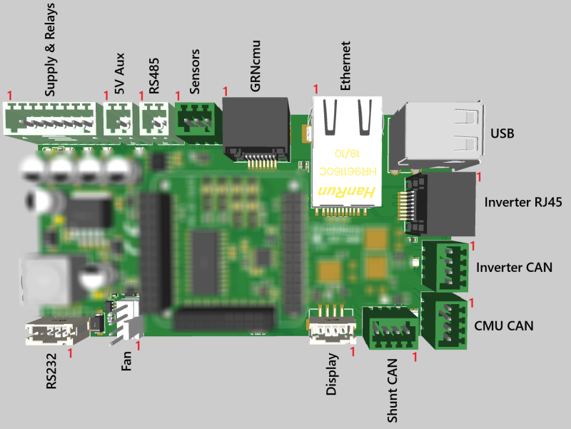
This page provides an overview of the wiring and pinout for the GRNbms MK3 Mini. Please refer to the respective Wiki pages for detailed information about CAN, RS485, and Modbus communication.
Power Supply
- Recommended input voltage: 11 – 14 V DC
- Power should be supplied via the designated power input pins (see pinout table below).
GRNcmu Connection
- The RJ45 port is directly compatible with a standard Ethernet cable.
- Designed for seamless plug-and-play connection with the GRNcmu Multi Mini module.
Fan Connector
- Compatible with standard 4-pin 12 V PC cooling fans.
- The GRNbms provides PWM control and tachometer feedback support.
Display Connector
- Ready to use with Nextion displays.
- Direct plug-in, no additional adapters required.
Pinout Overview
Supply & Relays
| 1 | Supply GND |
| 2 | Supply 12V |
| 3 | COM connection of the emergency stop switch |
| 4 | NC connection of the emergency stop switch |
| 5 | Main Relay - |
| 6 | Main Relay + |
| 7 | Precharge Relay - |
| 8 | Precharge Relay + |
5V Aux
| 1 | GND |
| 2 | 5V Output |
RS485
| 1 | RS485 A+ |
| 2 | RS485 B- |
Sensors
| 1 | 3.3V Output |
| 2 | Data |
| 3 | GND |
GRNcmu RJ45
| 1 | CAN2 High |
| 2 | CAN2 Low |
| 3 | 12V CMU |
| 4 | GND |
| 5 | GND |
| 6 | 12V CMU |
| 7 | 12V CMU |
| 8 | GND |
Inverter RJ45
| 1 | GND |
| 2 | 12V |
| 3 | - |
| 4 | 12V |
| 5 | GND |
| 6 | - |
| 7 | CAN1 High |
| 8 | CAN1 Low |
Inverter, CMU, Shunt - CAN
| 1 | GND |
| 2 | Inverter / CMU / Shunt - 12V |
| 3 | Inverter / CMU / Shunt - CAN Low |
| 4 | Inverter / CMU / Shunt - CAN High |
Display
| 1 | 5V |
| 2 | Display1 RX |
| 3 | Display1 TX |
| 4 | GND |
FAN
| 1 | GND |
| 2 | 12V |
| 3 | Tacho |
| 4 | PWM |
RS232
| 1 | GND |
| 2 | RS232 1 TX |
| 3 | RS232 1 RX |
| 4 | 12V |
mk3/minipinout.1749804751.txt.gz · Zuletzt geändert: 2025/06/13 08:52 von grnbms_tech