Relay Wiring – ReadBack Relays with STO
Only for GRNbms_MK3_HV_STO
Wiring Diagram
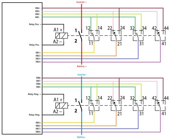
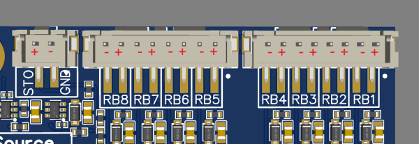
This diagram shows how to wire the relays with state feedback using 4 SPDT contacts per side (positive and negative). Feedback is routed through RB1–RB8 lines, each color-coded for clarity. The relays directly switch battery plus and minus without any precharge stage.
Safety Notes
- Relay coils must operate at 12 V.
- Recommended relay type: C320K/1000
- Only handle feedback wiring with HV disconnected!
- Check wiring regularly for secure connections.
STO Output (not shown in diagram)
A separate 24 V STO output is available for controlling inverters or similar devices.
Refer to your inverter’s documentation for proper connection details.