Inhaltsverzeichnis
GRNbms MK3 Mini – Wiring & Pinout
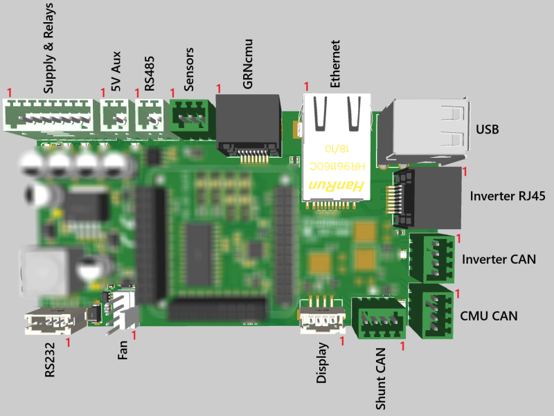
This page provides an overview of the wiring and pinout for the GRNbms MK3 Mini. Please refer to the respective Wiki pages for detailed information about CAN, RS485, and Modbus communication.
⚠️ Power over Ethernet (PoE) is not supported for GRN products and must not be used under any circumstances. The use of PoE with GRN products is strictly prohibited. Any non-compliance with this requirement may result in damage to the equipment. The company assumes no liability for any damages, malfunctions, or consequential losses arising from such misuse.
Power Supply
- Recommended input voltage: 11 – 14 V DC
- Power should be supplied via the designated power input pins (see pinout table below).
GRNcmu Connection
- The RJ45 port is directly compatible with a standard Ethernet cable.
- Designed for seamless plug-and-play connection with the GRNcmu Multi Mini module.
Fan Connector
- Compatible with standard 4-pin 12 V PC cooling fans.
- The GRNbms provides PWM control and tachometer feedback support.
RS232 Port
The RS232 port on the GRNbms MK3 Mini is directly compatible with Victron’s VE.Direct protocol, specifically for reading current sensors (shunts).
- Enables direct connection to Victron-compatible shunts without the need for converters.
- Ideal for monitoring real-time current flow in systems using Victron infrastructure.
Display Connector
- Ready to use with Nextion displays.
- Direct plug-in, no additional adapters required.
Connectors
1x 2.54-8P LCSC Part: C2927489
2x 2,54-2P LCSC Part: C2927483
3x 2,54-4P LCSC Part: C2927485
1x 2,54-3P LCSC Part: C2927484
Pinout Overview
Supply & Relays
| 1 | Supply GND |
| 2 | Supply 12V |
| 3 | COM connection of the emergency stop switch |
| 4 | NC connection of the emergency stop switch |
| 5 | Main Relay - |
| 6 | Main Relay + |
| 7 | Precharge Relay - |
| 8 | Precharge Relay + |
5V Aux
| 1 | GND |
| 2 | 5V Output |
RS232
| 1 | RS485 A+ |
| 2 | RS485 B- |
Sensors
| 1 | 3.3V Output |
| 2 | Data |
| 3 | GND |
GRNcmu RJ45
| 1 | CAN2 High |
| 2 | CAN2 Low |
| 3 | 12V CMU |
| 4 | GND |
| 5 | GND |
| 6 | 12V CMU |
| 7 | 12V CMU |
| 8 | GND |
Inverter RJ45
| 1 | GND |
| 2 | 12V |
| 3 | - |
| 4 | 12V |
| 5 | GND |
| 6 | - |
| 7 | CAN1 High |
| 8 | CAN1 Low |
Inverter, CMU, Shunt - CAN
| 1 | GND |
| 2 | Inverter / CMU / Shunt - 12V |
| 3 | Inverter / CMU / Shunt - CAN Low |
| 4 | Inverter / CMU / Shunt - CAN High |
Display
| 1 | 5V |
| 2 | Display1 RX |
| 3 | Display1 TX |
| 4 | GND |
FAN
| 1 | GND |
| 2 | 12V |
| 3 | Tacho |
| 4 | PWM |
RS232
| 1 | GND |
| 2 | RS232 1 TX |
| 3 | RS232 1 RX |
| 4 | 12V |